Using PID Control on Invertek Eco Drives
The Invertek Eco drive has a built-in Proportional-Integral-Differential (PID) controller, making it suitable for precise control applications like pressure, temperature, and flow rate management. This article will explain what PID control is, how to set it up on the Eco drive, and how to integrate external sensors and other useful features.
What is PID Control?

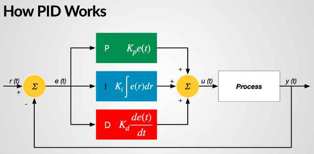
PID control is a closed-loop system where the drive adjusts motor speed based on the difference between a measured value (feedback) and a desired setpoint. The three components are:
Proportional (P): Reacts to the immediate difference between the setpoint and feedback.
Integral (I): Corrects over time to address any steady-state errors.
Differential (D): Predicts future changes to minimize overshoot, providing smoother control.
This combination makes PID controllers ideal for processes requiring high precision and stability, especially in systems with rapid changes or higher-order dynamics. By considering the rate of change of the error, PID controllers can pre-emptively counteract potential future errors, leading to smoother control and reduced overshoot. This also makes the controller suited for applications that have rapid changes or require high precision.
For instance, in a temperature control system, the derivative action helps prevent the temperature from oscillating around the setpoint, achieving a more stable temperature control. Another example is in robotics where precise and stable motion control is critical, the derivative term helps smooth out abrupt movements, leading to more accurate and stable control.
If your system is like what is described above, and you need a drive for it, the P2 and Eco drive will be best suited. For simpler slower systems, a PI controller is sufficient. This is available in the E3 drives. Read more about it in the following article: How to Use PI Control on Invertek E3 Drives

What Does a PID System Require?
To set up a PID system, you need:
Setpoint Signal: The target level you want to maintain (e.g., a specific pressure level).
Feedback Signal: Input from a sensor (e.g., a pressure transducer) that measures the actual system state. The drive adjusts motor speed based on the difference between the setpoint and feedback.
Setting Up PID Control on the Eco Drive
The following steps assume that the Optidrive Eco is in the default state – if parameters have been modified from their default state, this could affect the operation of the drive.
Motor data
The first step is to enter the motor nameplate data into the drive as follows:
P1-07 = Motor Rated Voltage
P1-08 = Motor Rated Current
P1-09 = Motor Rated Frequency
Auto-tune
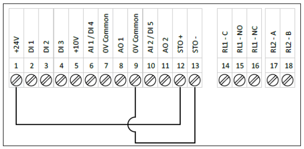
Once the motor data has been entered into the drive it is advisable to carry out an Auto-tune so that the motor stator resistance is measured. In order to carry out the auto-tune operation, there are minimum control terminal connections that must be made as shown below.

To enable the auto-tune, the extended parameters must be accessible which is achieved by setting:
P1-14 = 101
With the extended parameters now accessible, the auto-tune should be enabled by setting:
P4-02 = 1
Please Note: the motor must be stationary when carrying out the auto-tune
Enabling and configuring the PID
The following parameters in the Eco drive are essential for configuring PID control:
P1-12 (Primary Command Source): Set to 3 to enable PID mode.
P3-01 (PID Proportional Gain): Adjusts the system’s response to immediate changes. Higher values increase responsiveness but can cause instability if set too high.
P3-02 (PID Integral Time Constant): Controls how quickly the system corrects over time. Longer values are used for slower-changing systems to maintain stability.
P3-03 (PID Differential Time Constant): Reduces overshoot by limiting the rate of change of the output. Generally left at 0 for most pump and fan applications.
P3-04 (PID Operating Mode): Choose between:
0 Direct mode: Motor speed increases as feedback increases (e.g., pump control, compressor pressure control).
1 Inverse mode: Motor speed increases as feedback decreases (e.g., cooling fans, temperature control, condenser fa).
P3-05 (PID Setpoint Source): Defines where the setpoint originates:
0: Digital setpoint (set using P3-06).
1: Analog input 1 is used for variable setpoints / PID Reference.
2: Analog input 2 is used for variable setpoints / PID Reference.
P3-06 PID Digital Reference (set-point) value:
When P3-05 = 0, this sets the preset digital reference (set-point) for the PID controller.
For a simple system with a fixed set-point, the value for P3-06 can be calculated from the transducer range.
e.g. if a system is required to hold a constant pressure of 1.5 bar, and uses a transducer for feedback with measurement range 0-10 bar, the value of P3-06 can be calculated as
(1.5 bar x 100 %) / 10 bar = 15.0 %
AN-ODV-3-032 PID Closed Loop Feedback Control Applications 3
P3-10 PID Feedback Source Select:
The PID feedback can be selected from a variety of different sources:
Value | Feedback Signal | Format of the feedback |
0 | Analogue Input 2 (T10) | 0 – 100.0 % of P2-33 signal type selection |
1 | Analogue Input 1 (T6) | 0 – 100.0 % of P2-30 signal type selection |
2 | Motor load current | 0 – 100.0 % of P1-08 setting |
3 | DC Bus Voltage | 0 – 1000 Volts = 0 – 100.0 % |
4 | Analogue Input 1 – Analogue Input 2 (Differential) | 0 – 100.0 % of signal differential |
5 | Maximum (Analogue Input 1, Analogue Input 2) | 0 – 100.0 % of largest analogue signal |
By default, the feedback signal is set to Analogue Input 2 on terminal 10
The format of the feedback signal can be configured by setting the format of the analogue input in use as required. Most feedback transducers use the 4-20 mA format.
Using External Sensors for Feedback
External sensors can be connected to the Eco drive’s analog inputs. Common feedback sensors include:
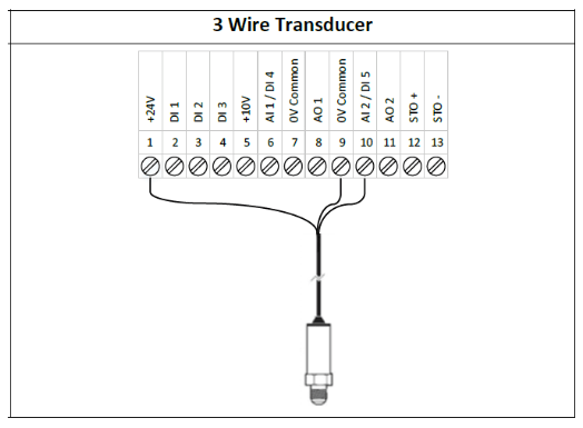
2-Wire Loop-Powered Transducers (4-20mA): Connect the power supply to pin 1 (+24V) and the transducer output to pin 10 (Analog Input 2). Ensure compatibility with the drive's input specifications.

3-Wire Transducers: Connect similarly, ensuring correct wiring for signal and power.

Set the feedback source using P3-10, which allows you to select inputs like Analog Input 1 or 2, motor current, or differential signals.
Activating the Standby Function
The Standby function reduces energy consumption by turning off the motor when it is not needed:
P3-14 (PID Standby Speed Threshold): Set slightly above the no-flow speed to enable standby when demand is low.
P2-27 (Standby Mode Delay): Determines the time the drive must operate at the minimum speed (P1-02) before entering standby.
P3-13 (PID Error Wake Up Level): Sets the deviation from the setpoint that will trigger the motor to restart after standby.
Adjusting Proportional Gain, Integral Time, and Differential Time
Fine-tuning these parameters ensures optimal system performance:
Proportional Gain (P3-01): Higher values make the system more responsive. Lower the gain if the system becomes unstable.
Integral Time (P3-02): Adjust to correct errors over time. Longer times suit slower systems, preventing oscillations.
Differential Time (P3-03): Use to minimise overshoot by smoothing rapid changes, but often set to zero for standard applications.
Monitoring system response through tools like the drive's feedback display or Optitools software allows for precise adjustments.
The PID control on the Invertek Eco drive enables efficient and precise management of various processes. By configuring essential parameters, integrating external sensors, and using features like standby mode, users can optimise system performance, save energy, and maintain desired operational levels. Proper setup and tuning of the PID parameters ensure stability and reliability in diverse applications, including pumps, fans, and temperature regulation systems.
For more information, please do not hesitate to contact ADM Systems. We will be able to walk you through the setup process and troubleshoot any issues you might be facing in your system.

