Running 4-20mA Loops over Long Distances
One of the key advantages 4-20mA loops offer is their ability to operate over longer distances.
Many industrial communication protocols, such as Ethernet I/P typically restrict you to cable runs of no more than 100m. This is not very useful for remote applications, where you need to communicate with devices that are located some distance away.
4-20mA loops can be used for cable runs of up to 500m, more in some cases, and offer fast response times, whilst being relatively noise-immune.
However, there are some important factors that you need to take into consideration in the design of your installation:
- The impedance of the instrument
- The network impedance
- The rated impedance of the twisted pair cable / Km

Why is Impedance Important?
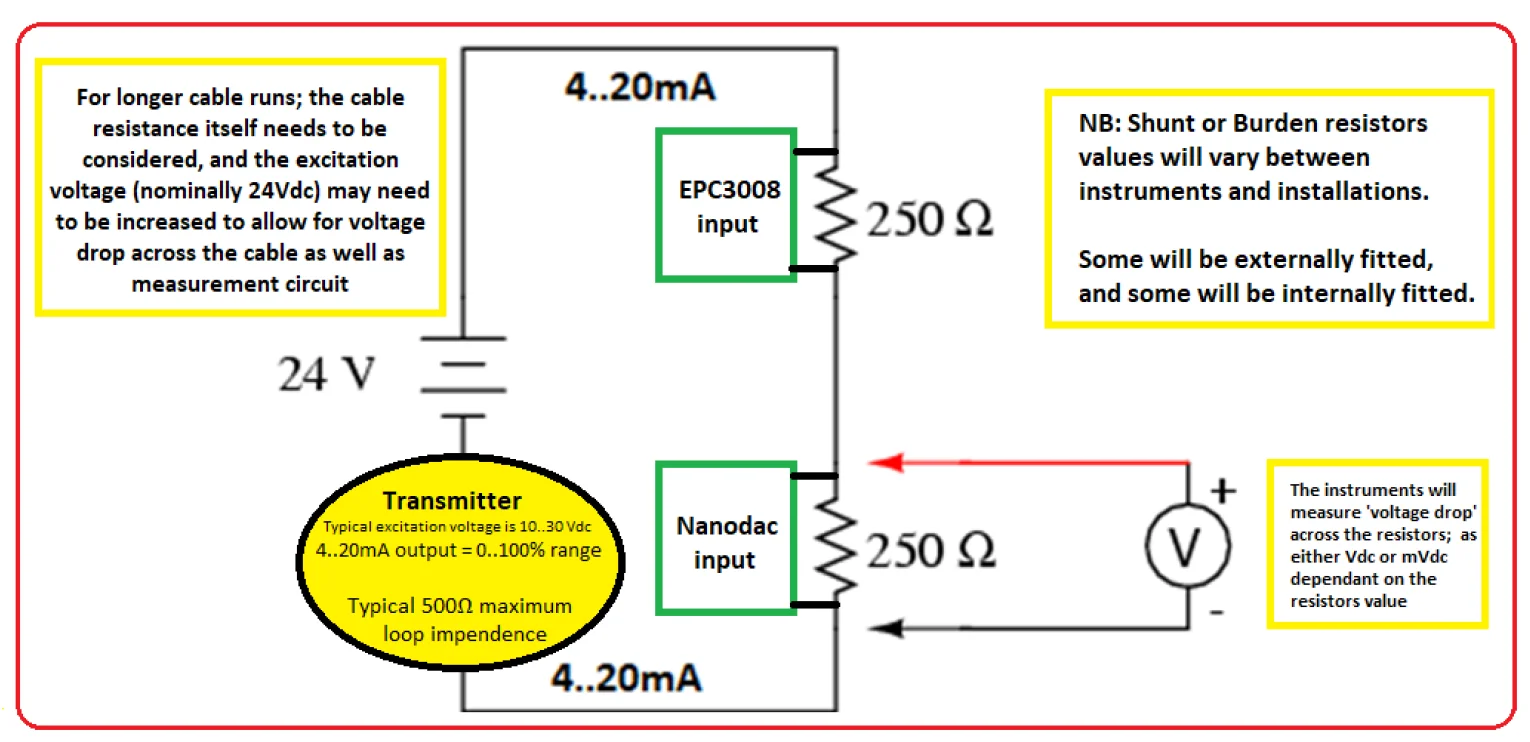
In reality, an instrument with a 4-20mA input is an instrument that accepts a voltage input, usually 1-5V. The instrument will use a set of resistors to convert the incoming current to a usable voltage, e.g. a 250-ohm resistor will create a voltage drop of 1 to 5 volts in a 4 to 20 mA loop, or 500 ohm 2 to 10 volts.
Some instruments have these resistors built into them. Others, such as Eurotherm’s controllers have them external to the unit. This is to allow the installer to configure the controller as either a voltage input device or a current input device. The other reason the resistors may be external to the controller is to retain the loop integrity if the controller has been removed. For example, Eurotherm controllers have a mounting sleeve, which is where the resistors are accommodated. When the controller is removed from the sleeve the resistors remain in situ. This solution is particularly useful if you have built redundancy into your design.
Excessive impedance in the loop will affect the voltage conversion, as the actual voltage arriving at the instrument will be lower than expected due to voltage drop. Eurotherm overcome this problem by using lower shunt values such as 2.49 ohms thus only dropping 9.96 to 49.8 mV on the 2000 & 3000 series instrument.
Selecting an Appropriate Transmitter / Transducer
When selecting a 4-20mA transmitter or transducer, you need to check its rated loop impedance. The total impedance in your installation must be lower than this value. However, check the transmitter data sheet to see if there is a minimum resistance required in order for it to operate.
Check the Instrument Impedance
You will need to check the rated impedance of the resistors used in your instrument (controller) to ensure these are lower than the rated loop impedance of your device.
Calculate the Total Cable Impedance
Check the rated impedance of the cable / Km that you intend to use and calculate the impedance across the total length of the cable. This is determined by a wire gauge. Typically, 20 Ohm /km is considered to be ideal.
You need to then add this to the rated impedance of the instruments. The total needs to be less than the rated loop impedance of your transmitter.
If you find that your combined cable and instrument impedance is higher than the rated loop impedance of your 4-20mA transmitter then there are a couple of solutions available to you:
- Select a cable with a lower impedance. In other words, one with a larger wire diameter.
Or
- Select an alternative 4-20mA transmitter with a higher-rated loop impedance.
Please do not hesitate to contact ADM Instrument Engineering if you would like help with selecting suitable instruments and transmitters for use in 4-20mA loops being used over long distances.
WAS THIS INFORMATION USEFUL?
Why not share it with you industry peers on LinkedIn? Simply click on the blue LinkedIn share icon below.
