Optimising Retrofit Applications with Invertek Drives for Permanent Magnet and Brushless DC Motors
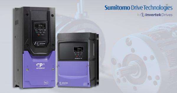
Retrofitting with Invertek’s Optidrive P2 drive allows for flexible and efficient operation of Permanent Magnet (PM) and Brushless DC (BLDC) motors. These motor types provide higher efficiency and lower operating costs than induction motors, especially in high-torque, low-speed applications.
In this article, we’ll cover essential setup parameters, calculating motor-rated voltage, optimising motor operation, and troubleshooting tips for effective implementation in retrofit scenarios.

Key Motor Parameters for Operation
When configuring the Optidrive P2 for PM or BLDC motors, accurately setting specific motor parameters ensures optimal drive performance:
1. Motor Rated Voltage (P1-07): This parameter is critical as it represents the Back Electromotive Force (Back EMF) at rated speed, often referred to as the nominal voltage. For motors with only phase-to-neutral data, calculate phase-to-phase voltage by multiplying by √3 (approximately 1.732). Accurate setting of P1-07 prevents motor overheating and ensures efficiency, as incorrect values lead to unstable operation.
2. Motor Rated Current (P1-08): The motor’s continuous phase current, or nominal current, must be entered into P1-08. This value acts as a current limit to protect the motor against overcurrent damage, especially under heavy load or variable-speed conditions.
3. Motor Rated Frequency (P1-09): This frequency corresponds to the speed required for the motor’s rated speed and can be derived if the motor's pole count is known:

For example, an 8-pole motor at 3000 RPM would require a frequency of 200 Hz.
4. Motor Rated Speed (P1-10): This value should reflect the motor’s rated speed in RPM, aligning with the frequency set in P1-09 to ensure the motor operates at full efficiency without overloading or undershooting speed targets.
5. Switching Frequency (P2-24): For smooth PM motor operation, a switching frequency of at least 16kHz is recommended. Higher switching frequencies reduce audible noise and improve motor smoothness but may increase drive heating, necessitating de-rating of the drive if use over extended periods.
Calculating Motor Rated Voltage
For calculating P1-07, use the Back EMF or voltage constant provided by the motor manufacturer, typically presented as voltage per 1000 RPM. For example, a motor with a constant of 50 V/1000 RPM running at 3000 RPM would require:

Ensure that the calculated voltage value reflects phase-to-phase requirements, as entering incorrect values can impact efficiency and motor safety.
Optimising Motor Operation
To maximise performance in varying load or low-speed conditions, the following settings allow fine-tuning of the motor response:
1. Low-Speed Torque Boost (P7-14 and P7-15): These parameters apply a current boost at low speeds to aid rotor alignment and start-up torque. Set P7-14 (Low Frequency Torque Boost) to around 10%, which increases the motor current by up to 10% in the lower frequency range. Adjust this value if the drive encounters start-up trips; too high a value can cause overheating, so monitoring motor temperature is essential. Define the frequency range for torque boost using P7-15. Typically, setting it to 10% of P1-09 provides reliable low-speed performance.
2. Motor and Load Inertia Ratio (P7-10): The inertia ratio between the motor and load affects system responsiveness. Calculate P7-10 as follows:

Accurate inertia ratio helps the drive controller match torque to load changes smoothly, preventing oscillations and improving acceleration.
3. Speed Loop Gains (P4-03 and P4-04): PM motor control benefits from higher proportional and integral gains for precise speed management. Set P4-03 (proportional gain) to 50% and P4-04 (integral time constant) to 100 ms. Adjust these values in small increments to refine motor responsiveness and prevent system oscillations.
4. Magnetising Time (P7-12): This parameter sets the magnetising delay at startup, enabling proper rotor alignment. If start-up delays or trips occur, increasing P7-12 can stabilise the start by providing more time for magnetisation. This ensures smooth, consistent operation from startup through regular speed ranges.

Troubleshooting Common Issues
For retrofitting, it’s essential to monitor the setup closely and use these tips to resolve common issues effectively:
1. Auto-Tune Failures: Auto-tuning is crucial for calibration, as it measures motor-specific parameters such as stator resistance and inductance. Ensure values in P1-07 to P1-10 are correct before starting auto-tune, as misconfigurations lead to calibration failure or unstable operation.
2. Low-Speed Torque Issues: If torque performance is low at startup, adjust torque boost parameters (P7-14 and P7-15). Make incremental adjustments to increase low-speed torque without exceeding thermal limits and confirm that other parameters (such as rated current) align with the motor’s nominal data.
3. Overheating and High Current: High current draw can cause motor overheating, potentially damaging both the drive and motor. Verify that P1-07 and P1-08 are set to the manufacturer’s nominal values. Excessive low-speed boost can also contribute to heating, so adjust torque boost (P7-14 and P7-15) to balance torque and heat.
4. Unstable Motor Speed: If motor speed is erratic, verify that switching frequency (P2-24) is set to 16kHz or higher. Recheck motor-rated parameters in P1-07 to P1-10, and adjust speed loop gains (P4-03 and P4-04) to stabilise control. Fine-tuning these parameters can significantly improve motor response and smoothness in operation.
5. Inadequate System Dynamics: Poor response times or slow dynamics may indicate a need for adjustments in speed loop gains or load inertia ratios. Increasing the proportional gain (P4-03) improves response but may lead to oscillations if set too high. Gradually adjust the integral gain (P4-04) to reduce steady-state errors.
By following these setup guidelines and troubleshooting strategies, Invertek’s Optidrive P2 can deliver precise, efficient performance for PM and BLDC motors in retrofit applications. Accurate parameter configuration and ongoing adjustments allow for robust motor control, enhanced energy savings, and improved performance across various industrial applications.
Contact ADM here if you would like any further information about Invertek Optidrive P2.

