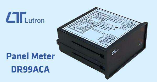
How to Set Your Lutron Panel Meter DR99ACA
We know why you are here. You have recently acquired a Lutron Panel Meter, and can’t quite set it up?Allow us to remove the guessing game in your configuration.
These steps apply specifically to DR99ACA, but with some adjustments, can also apply to panel meters DR99ACV, DR99DCA, DR99DCV.
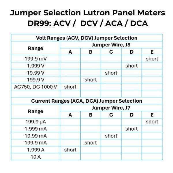
You can refer to the table below, and to the attached data sheets from each product at the bottom of this article, for more information.
Configuration Steps
Power off the device - Ensure that the meter is turned off and disconnected from any power source to prevent damage or injury.
Locate the jumper settings
Carefully open the panel meter's casing.
Look for a section on the PCB (Printed Circuit Board) labelled as "Range" or "Jumper Configuration."
Determine the current range and decimal placement
The DR99ACA supports ranges such as 199.9 μA, 1.999 mA, 19.99 mA, 199.9 mA, 1.999 A, and 10 A.
Each range has a corresponding jumper position that dictates how the input is scaled and displayed. You can refer to the chart below for specifics.
Set the jumpers
Consult the device's manual or the PCB markings to identify the correct jumper settings for your desired range.
Use a needle-nose pliers or your fingers to adjust the jumper wires to the appropriate position.

Verify the decimal placement
The decimal placement is typically adjusted automatically based on the range selected. However, some meters allow separate jumper settings for this.
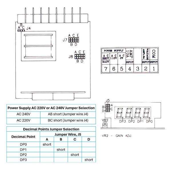
Reassemble and power on
Once the jumper wires are set, reassemble the casing, ensuring all connections are secure.
Power on the device and check the display for the correct range and decimal placement.
Example of Range and Decimal Correspondence
199.9 μA - Decimal point should be after the first digit.
1.999 mA - Decimal point should be after the second digit.
10 A - No decimal point.
Things to note:
1. If you are using AC 220V/240V voltage, pins 6 and 7 in the picture must be changed to pins 5 and 7.
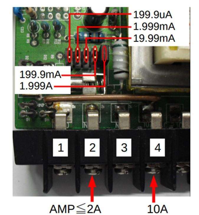
2. When the series current is ≧ 2A, pins 1 and 2 in the picture must be changed to pins 1 and 4.
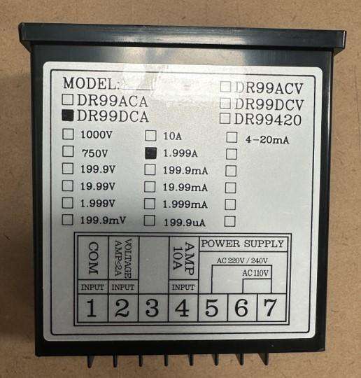
3. If you are using 10A, you need to change the resolution to DP2.
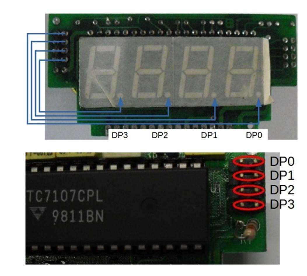
4. If you are using other ranges (199.9 mA - 199.9uA), please refer to the settings below.
If you need more information or have any questions, please contact our team on 1300 236 467, @email or through our website.
